
On an architectural plan, a window is not drawn as it appears in real life. Instead, it is represented by a combination of lines, arcs and dimensions that indicate its type, size and opening mechanism. Understanding these graphic conventions makes it possible to read plans unambiguously and produce documents that everyone involved in a construction project can use.
Graphic conventions for windows in plan view
A plan view shows the building from above, as if cut through at a height of about one metre. At this level, a window appears as a break in the wall thickness, represented by two parallel lines indicating the glazing.
These two lines are drawn within the thickness of the wall. The space between them represents the glass pane, while the lines themselves represent its surfaces. A guide explaining how to represent a window on an architectural plan provides a practical illustration of these conventions.
The opening direction is shown by an arc with a radius corresponding to the width of the sash. The arc starts at the pivot point (the hinge) and traces the sash’s swing. A double-casement window has two symmetrical arcs. A fixed window has no arc: only the two glazing lines are shown, sometimes crossed out to avoid any confusion.
- French casement window (opens inward): the arc is drawn toward the inside of the building, on the room side.
- Tilt-and-turn window: a second symbol (often a triangle or an upward-pointing arrow) is added to the arc to indicate the top-tilt position.
- Sliding window: no arc is shown; instead, a horizontal arrow indicates the direction of travel, with a solid line for the fixed sash and a dashed line for the moving sash.
- Pivot window: a triangle pointing outward, sometimes accompanied by an arrow, indicates rotation around a central horizontal axis.
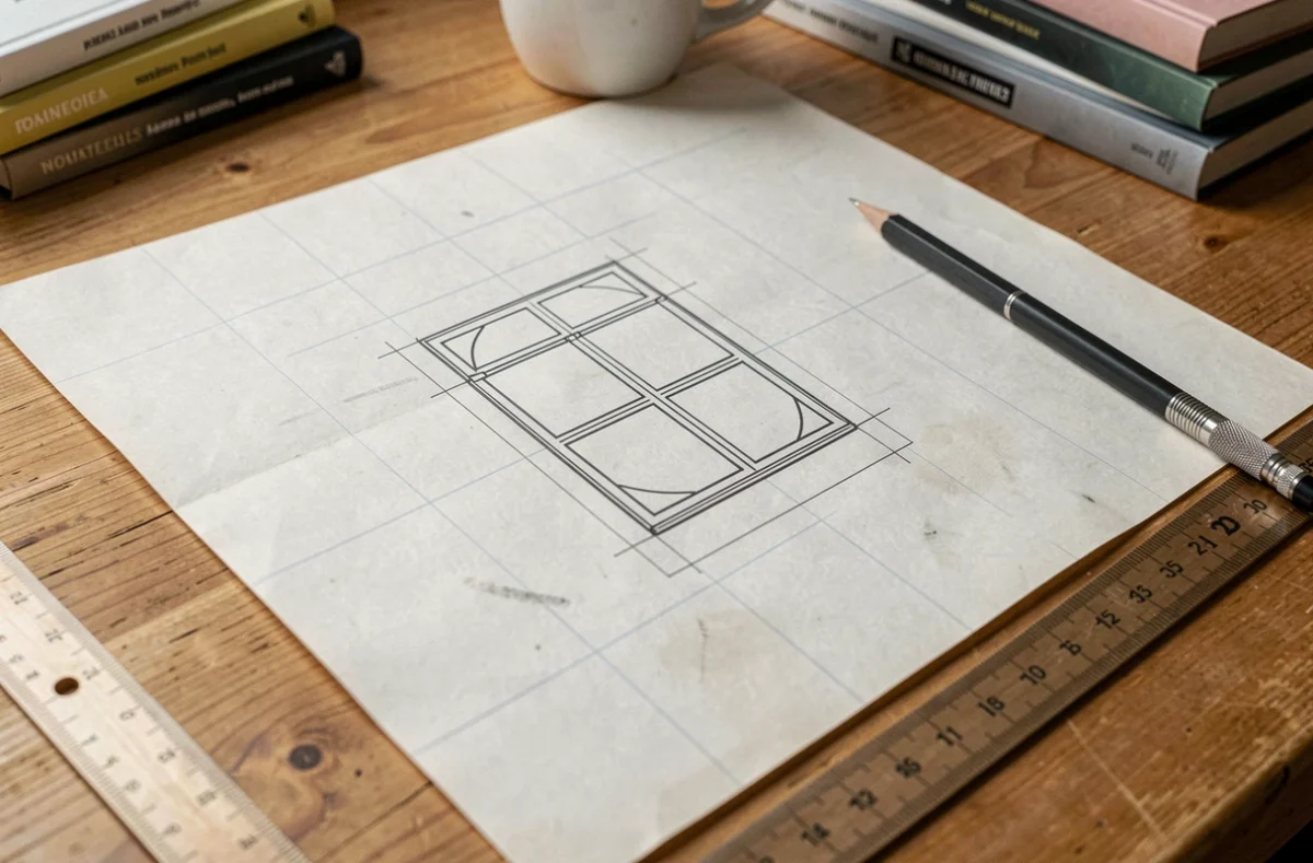
Window dimensions and identification on an architectural plan
The symbol alone is not enough. Each window is marked with dimensions specifying its width, height and sill height (the distance from the finished floor to the bottom of the window frame). These three values are grouped in a label or written directly next to the symbol.
The standard notation uses the format width x height, expressed in centimetres. The sill height is often shown below or in parentheses. On a 1:50 scale plan, clarity requires these details to be presented consistently for every opening.
A letter- or number-based identification system labels each window. This reference also appears in the window schedule, a document accompanying the plan that lists the type (casement, sliding, fixed), material (wood, PVC, aluminium), glazing and required thermal performance for each opening. The schedule avoids cluttering the drawing while keeping all the technical information in one place.
Sill, lintel and reveal: three dimensions not to confuse
The sill is the section of wall beneath the window. The lintel is the structural element above it. The reveal is the side recess, or rebate, into which the frame fits. On a detail drawing or vertical section, these three elements are shown separately, each with its own dimension.
Confusing the reveal with the width of the window opening is a common mistake. The reveal width is always less than the rough opening width, as it accounts for the recesses on either side.
Vertical section and window installation detail
The plan view shows the location and type of opening, but not how the window fits into the wall. That is shown in the vertical section, which cuts through the wall and window thickness.
This section shows the frame (the part fixed to the structural wall), the sash (the moving part) and the sill upstand (the small raised edge beneath the window that prevents water from getting in). It also shows the installation method.
- Face-fixed installation: the frame is fixed against the inside face of the wall, on the insulation side. This is the most common method in new builds with internal insulation.
- Recessed installation (or reveal installation): the window is fitted within the thickness of the wall. This is common in older buildings with thick walls.
- Rebate installation: the frame is set into a groove cut into the reveal. This is suitable for renovations where the existing frame is removed.
NF DTU 36.5 governs the installation of windows and external doors and sets out requirements for sealing, fixing and joint treatment. On a construction detail drawing, the sealing method (impregnated foam, sealant or membrane) must be specified.

Windows on renovation plans: distinguishing existing features from proposed work
On a renovation plan, existing features, demolition work and new construction must be clearly distinguished. The most common convention uses thin lines for existing elements to be retained, hatching or solid fills for elements to be demolished, and thick lines for new work.
The condition of the existing frame is a decisive factor. Keeping an old frame reduces the scope of the work, but it must be structurally sound. Removing the frame entirely changes the opening dimensions and means the plaster, reveals and sometimes the lintel must be repaired. The site survey must therefore be accurate and record clearances, out-of-plumb walls and the condition of the sills.
A renovation plan that does not distinguish between these phases can lead to incorrect window orders or unexpected issues during removal. Three graphic layers (existing, demolition and proposed work) are enough to eliminate any ambiguity.
Window orientation and additional information on the plan
Window placement is not just a matter of aesthetics or interior layout. Glazed areas and their orientation directly affect solar gains, natural light and the risk of summer overheating—all factors assessed under RE2020 through the calculation of bioclimatic needs.
A plan should include a north arrow and, where relevant to the project, the planned solar shading (brise-soleil, shutters or an overhang). These elements are not part of the window symbol itself, but they add to the information shown on the plan and avoid the need to cross-reference other documents.
A clear plan is one where every window can be understood without referring back to the specification. The opening symbol, dimensions, reference, installation method and orientation form a coherent whole. When this information is brought together from the initial sketch, later stages (obtaining quotes from window installers, submitting a permit application and construction) can proceed without any loss of information.